
2014年8月30日土曜日
2013年12月2日月曜日
XBEE : RECEIVER
XBEE RECEIVER BOARD
XBEE is connected to PIC and send the command to the other XBEE via USART.
IR-LED can output signal for controlling TV or other IR-controllable appliances and it is controlled by PWM.
Carrier is 40kHz so PWM frequency is set to that value and the duty ratio is 1:3.

PCB is Arrived and Assembled
PCB arrived which I ordered on Nov.8th.
I only ordered 5pcs but arrived amount is 11pcs!
Trying samples were added to my order? Anyway I satisfied its quality. There are no pattern short and wrong drill position. Silk is not beautiful but there is no inconvenience.

Below figure shows my assembled results. Seemed to be working correctly.

In this time purchase, It needs 16 days to deliver from their shipment. From order it needs 3 weeks.
I only ordered 5pcs but arrived amount is 11pcs!
Trying samples were added to my order? Anyway I satisfied its quality. There are no pattern short and wrong drill position. Silk is not beautiful but there is no inconvenience.
Below figure shows my assembled results. Seemed to be working correctly.
In this time purchase, It needs 16 days to deliver from their shipment. From order it needs 3 weeks.
2013年11月9日土曜日
Apple keyboard with numeric key + Track pad
Apple keyboard with numeric key + Track pad
Apple keyboard with numeric key is a little bit large when using with track pad.
I made mistake that I should buy wireless compact one only for 20 dollar...
Before replacing it, I make track pad board for reducing space.
I cut acrylic board and bend it like below picture.
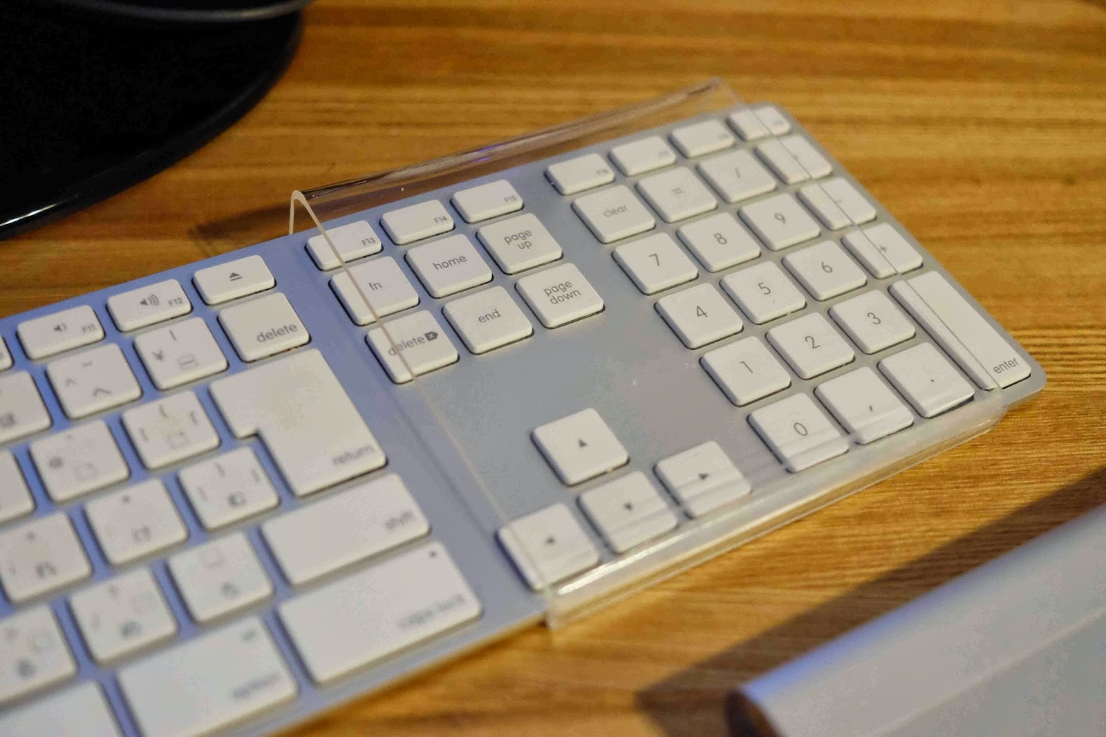
Then, the track pad can be put and the space can be reduced.

But, best for looking is using wireless one.
2013年11月8日金曜日
Wake up timer : circuit is fixed
Wake up timer : circuit is fixed
Now I have finished designing circuit and below is snapshot of its discrete one.

This wake up timer has below functions:
1. Light up
LED light is turned on step by step by PWM driving before wake up buzzer is ringing.
The time to lighting up can be changed by setting. This function can let user easy wake up like sunrise.
2. Buzzer
Sound is generally changed from small sound to large one for comfortable wake up.
Buzzer sound is changeable because IC for buzzer is PIC16F88.
3. TV control
XBEE is equipped. Very rich. Then, this board can send the command to its counterpart via USART. The other XBEE receives the command and send the IR signal for TV control such as powering up and making sound large. The IR signal of my TV is already analyzed.
In the near future, all of the house appliance controlled by IR can be under control of this board.
I have designed PCB board by eagle and it will be arrived in couple of weeks. Then I will start soldering...
2013年8月10日土曜日
Pic : RS232 communication
RS232 communication on PIC
I will make the remote controller device by using XBEE. Before that, PC and PIC communication is tested.

18f2320 is used.
RX/TX port are used and TRISCbits.RC7 is set to be input I/O and TRISCbits.RC6 is set to output one. Also TRISCbits.RC6 is set to high.
Please check below setting is set correctly.
• SPEN (RCSTA<7>) bit must be set (= 1)
• TRISC<7> bit must be set (= 1)
• TRISC<6> bit must be cleared (= 0)
Below program needs windows' hyper terminal input.
10MHz clock is multiplied by config. HSPLL so clock is 40MHz.
Then, baud rate is 115.2kHz.
//////////////////////////////////
//main program
//////////////////////////////////
#include <p18f2320.h>
#include <i2c.h>
#include <usart.h>
#include "i2cLCD.h"
#include "wait.h"
#pragma config OSC=HSPLL, FSCM=OFF, IESO=OFF, PWRT=ON
#pragma config BOR=ON, BORV=27, WDT=OFF, WDTPS=1024
#pragma config MCLRE=ON, PBAD=DIG, CCP2MX=C1
#pragma config STVR=OFF, LVP=OFF, DEBUG=OFF
#pragma config CP0=OFF, CP1=OFF, CP2=OFF, CP3=OFF, CPB=OFF
#pragma config CPD=OFF, WRT0=OFF, WRT1=OFF, WRT2=OFF, WRT3=OFF
#pragma config WRTB=OFF, WRTC=OFF, WRTD=OFF, EBTR0=OFF
#pragma config EBTR1=OFF, EBTR2=OFF, EBTR3=OFF, EBTRB=OFF
void main(void)
{
char test[]="AQM0802A";
char inputFromPC[] = "From PC";
char inputMsg[]="\r\nInput 5 characteristic= ";
char bufLcd[10]={0,0,0,0,0,0,0,0,0,0};
//I2C initialization
TRISC = 0x18;
SSPADD = 24; //MCLK40MHz / (4*(SSPAD+1)) = 400khz
SSPCON1 = 0b00101000;
wait_ms(100);
lcdIni();
lcdCommand(LCD_1ST_LINE);
lcdPrintSting(test);
wait_ms(200);
lcdCommand(LCD_CLEAR);
//USART
TRISC |= 0x80;
LATC = 0x40;
RCSTAbits.SPEN=1;
OpenUSART(USART_TX_INT_OFF & USART_RX_INT_OFF &
USART_ASYNCH_MODE & USART_EIGHT_BIT &
USART_CONT_RX & USART_BRGH_HIGH,21);
while(1)
{
putsUSART(inputMsg);
getsUSART(bufLcd,5);
lcdCommand(LCD_CLEAR);
wait_ms(2);
lcdCommand(LCD_1ST_LINE);
lcdPrintSting(inputFromPC);
lcdCommand(LCD_2ND_LINE);
lcdPrintSting(bufLcd);
}
}
Pic : LCD AQM0802A driving
Driving AQM0802A LCD
I have bought AQM0802A which can be driven by the I2C bus.
Driving voltage is 3.3V so PIC is also driven by 3.3V for connecting by I2C.

Below is the example code of driving the LCD.
This ic has the function of continuous sending, but below code is only sending each byte every time.
Sending each byte needs slave address, control byte and data byte.
By setting control byte, clear, changing cursor and etc can be implemented like SD1602 display.
This ic only needs 2 wire from Pic so we can use lots of port comparing with SD1602.
///////////////////
i2cLCD.h
///////////////////
#ifndef I2C_FUNCTION
#define I2C_FUNCTION
#define SLV_ADDR 0x7C
#define LCD_CLEAR 0x01
#define LCD_1ST_LINE 0x80
#define LCD_2ND_LINE 0xC0
int lcdCommand(char cmd);
int lcdIni(void);
int lcdByteWrite(unsigned char cmd, unsigned char data);
int lcdPrintSting(char* str);
#endif
///////////////////
i2c functions
///////////////////
#include <p18f2320.h>
#include <delays.h>
#include <i2c.h>
#include "i2cLCD.h"
#include "wait.h"
int lcdPrintSting(char* str)
{
char byteRsOn=0x40;
//Send buffer data
while(*str!=0x00)
{
lcdByteWrite(byteRsOn, *str);
str++;
}
return 0;
}
int lcdCommand(char cmd)
{
lcdByteWrite(0x00, cmd);
return 0;
}
int lcdIni(void)
{
OpenI2C(MASTER,SLEW_OFF);
//Function set
lcdByteWrite(0x00, 0x38);
wait_ms(1);
//Function set, IS=1
lcdByteWrite(0x00, 0x39);
wait_ms(1);
//Internal osc freq. setting
lcdByteWrite(0x00, 0x14);
wait_ms(1);
//Contrast set
lcdByteWrite(0x00, 0x70);
wait_ms(1);
//Power/ICON/Contrast control
lcdByteWrite(0x00, 0x56);
wait_ms(1);
//Follower control
lcdByteWrite(0x00, 0x6C);
wait_ms(300);
//Function set
lcdByteWrite(0x00, 0x38);
wait_ms(1);
//Dispaly on/off control
lcdByteWrite(0x00, 0x0C);
wait_ms(1);
//Clear dispaly
lcdByteWrite(0x00, 0x01);
wait_ms(2);
return 0;
}
int lcdByteWrite(unsigned char cmd, unsigned char data)
{
//Start Condition
IdleI2C();
StartI2C();
while(SSPCON2bits.SEN){;}
//Write Slave Address wtih Write mode
if(WriteI2C(SLV_ADDR)<0){return -1;}
IdleI2C();
//Send control byte
if(WriteI2C(cmd)<0){return -2;}
IdleI2C();
//Write data
if(WriteI2C(data)<0){return -3;}
//Send Stop
IdleI2C();
StopI2C();
while(SSPCON2bits.PEN);
Delay10TCYx(4);
return 0;
}
/////////////////////////////////
//main: 10MHz external OSC is used
/////////////////////////////////
void main(void)
{
char test[]="AQM0802A";
//I2C initialization
TRISC = 0x18;
SSPADD = 24; //MCLK40MHz / (4*(SSPAD+1)) = 400khz
SSPCON1 = 0b00101000;
wait_ms(100);
lcdIni();
lcdCommand(LCD_1ST_LINE);
lcdPrintSting(test);
lcdCommand(LCD_2ND_LINE);
lcdPrintSting(test);
while(1)
{
}
登録:
コメント (Atom)